
Bypass Capacitor / De-Coupling capacitor
- Most ICs suffer performance degradation of some type if there is ripple and/or noise on the power supply pins. A digital IC will incur a reduction in its noise margin and a possible increase in clock jitter. For high performance digital ICs, such as microprocessors and FPGAs, the specified tolerance on the supply (±5%, for example) includes the sum of the dc error, ripple, and noise. The digital device will meet specifications if this voltage remains within the tolerance.
- A bypass capacitor stores an electrical charge that is released to the power line whenever a transient voltage spike occurs. It provides a low-impedance supply, thereby minimising the noise generated by the switching outputs of the device.
- A basic requirement for all electronic circuits is the inclusion of bypass, or decoupling, capacitors. These devices reside across the positive supply to ground, as close as possible to the supply pin of the active device.

- Capacitors across VCC/GND keep the voltage more constant. When Multi-Mhz Microcontroller switches a bunch of outputs from high to low, it will draw from the power supply, causing the voltage to fall.Power supplies are slow, they take roughly 10 us to respond & to do something to correct the drooping voltage. Decoupling capacitors add fast "charge storage" near the IC. So when your micro switches the outputs, instead of drawing charge from the power supply, it will first draw from the capacitors. This will buy the power supply some time to adjust to the changing demands.
- Eg: When Microcontroller is powered up (VCC=5V), the capacitor is charged to capacity and waits until there is a change in the voltage between VCC and GND (VCC = 4.5V). At this point, the capacitor will discharge to try and bring the voltage back to the level of charge inside the capacitor (5V). This is called "smoothing" (or at least that is what I call it) because the change in voltage will be less pronounced. Ultimately, the voltage will not ever return to 5V through a capacitor, rather the capacitor will discharge until the charge inside it is equal to the supply voltage (to an equilibrium). A similar mechanism is responsible for smoothing if VCC increases too far beyond its average (VCC=5.5V perhaps)

- The "speed" of capacitors varies. Basically, smaller capacitors are faster; inductance tends to be the limiting factor, which is why everyone recommends putting the caps as close as possible to VCC/GND.Ceramic capacitors are better for high-speed decoupling because they are "faster". The bulk (polarized) tantalum capacitors are only for lower frequency because they are "slow" (due to ESR -- think small RC filter inside the capacitor).
- Typically, manufacturers include suggested bypass-capacitor values in their data sheets, but you can also determine the proper value on your own. For instance, with microcontrollers or microprocessors, you can calculate the bypass-capacitor value when you know the typical rise and fall times (tRISE) of the device signals. You also need the controller's average operating current (IAVE). These quantities are in the product-data-sheet tables. You finally need to define the maximum voltage-ripple noise (VRIPPLE) that your power-supply trace can tolerate. Using these values, you can determine noise frequency with the formula fNOISE=1/(2×tRISE); approximate surge current with the formula ISURGE=IAVE×fNOISE/fMICRO, where fMICRO is the clock frequency of the controller; and calculate bypass-capacitor value with the formula CBYPASS=ISURGE/(2×π×fNOISE×VRIPPLE).
- The traditional way to specify the sensitivity of an analog IC to power supply variations is the power supply rejection ratio (PSRR). For an amplifier, PSRR is the ratio of the change in output voltage to the change in power supply voltage, expressed as a ratio (PSRR) or in dB (PSR). PSRR can be referred to the output (RTO) or referred to the input (RTI). The RTI value is equal to the RTO value divided by the gain of the amplifier.

- Figure above shows how the PSR of a typical high performance amplifier (Eg: AD8099) degrades with frequency at approximately 6 dB/octave (20 dB/decade). Curves are shown for both the positive and negative supply. Although 90 dB at dc, the PSR drops rapidly at higher frequencies where more and more unwanted energy on the power line will couple to the output directly. Therefore, it is necessary to keep this high frequency energy from entering the chip in the first place. This is generally done with a combination of electrolytic capacitors (for low frequency decoupling),ceramic capacitors (for high frequency decoupling), and possibly ferrite beads.
- Power supply rejection of data converters and other analog and mixed-signal circuits may or may not be specified on the data sheet. However, it is very common to show recommended power supply decoupling circuits in the applications section of the data sheet for practically all linear and mixed-signal ICs . These recommendations should always be followed in order to ensure proper operation of the device.
- Low frequency noise requires larger electrolytic capacitors which act as charge reservoirs to transient currents. High frequency power supply noise is best reduced with low inductance surface mount ceramic capacitors connected directly to the power supply pins of the IC. All decoupling capacitors must connect directly to a low impedance ground plane in order to be effective. Short traces or vias are required for this connection to minimise additional series inductance.
- Ferrite beads (non-conductive ceramics manufactured from the oxides of nickel, zinc, manganese, or other compounds) are also useful for decoupling in power supply filters. At low frequencies (<100 kHz), ferrites are inductive; thus they are useful in low-pass LC filters. Above 100 kHz,ferrites becomes resistive (high Q). Ferrite impedance is a function of material, operating frequency range, dc bias current, number of turns, size, shape, and temperature. The ferrite beads may not always be necessary, but they will add extra high frequency noise isolation and decoupling, which is often desirable. Possible caveats here would be to verify that the beads never saturate, especially when op amps are driving high output currents. When a ferrite saturates it becomes nonlinear and loses its filtering properties. Note that some ferrites, even before full saturation occurs, can be nonlinear. Therefore, if a power stage is required to operate with a low distortion output, the ferrite should be checked in a prototype if it is operating near this saturation region.

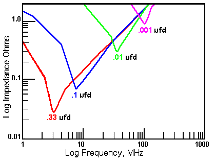
- Also where the caps are placed can have a big effect on how well bypass filtering work. The larger caps work better by placement at where power enters the board or right at the output of a voltage regulators, where as the smaller popular .1ufd caps are usually more effective mounted right at the Vcc terminals of any ICs being protected.
REAL CAPACITORS AND THEIR PARASITIC'S


- Figure above shows a model of a non-ideal capacitor. The nominal capacitance, C, is shunted by a resistance, RP, which represents insulation resistance or leakage. A second resistance, RS (equivalent series resistance, or ESR), appears in series with the capacitor and represents the resistance of the capacitor leads and plates.
- Inductance, L (the equivalent series inductance, or ESL), models the inductance of the leads and plates. Finally, resistance RDA and capacitance CDA together form a simplified model of a phenomenon known as dielectric absorption, or DA. When a capacitor is used in a precision application, such as a sample-and-hold amplifier (SHA), DA can cause errors. In a decoupling application, however, the DA of a capacitor is generally not important.
- Figure below shows the frequency response of various 100 μF capacitors.

- Theory tells us that the impedance of a capacitor will decrease monotonically as frequency is increased. In actual practice, the ESR causes the impedance plot to flatten out. As we continue up in frequency, the impedance will start to rise due to the ESL of the capacitor. The location and width of the "knee" will vary with capacitor construction, dielectric and value. This is why we often see larger value capacitors paralleled with smaller values. The smaller value capacitor will typically have lower ESL and continue to “look” like a capacitor higher in frequency. This extends the overall performance of the parallel combination over a wider frequency range.
- The self-resonant frequency of the capacitor is the frequency at which the reactance of the capacitor (1/ωC), is equal to the reactance of the ESL (ωESL). The minimum impedance is determined by the ESR, and the high frequency region is determined by the ESL (which in turn is strongly affected by package style).
TYPES OF DECOUPLING CAPACITORS
Figure below shows the various types of popular capacitors suitable for decoupling.

- The electrolytic family provides an excellent, cost effective low-frequency filter component because of the wide range of values, a high capacitance-to-volume ratio, and a broad range of working voltages. It includes general-purpose aluminum electrolytic switching types, available in working voltages from below 10 V up to about 500 V, and in size from 1 μF to several thousand μF (with proportional case sizes).
- All electrolytic capacitors are polarized, and thus cannot withstand more than a volt or so of reverse bias without damage. They have relatively high leakage currents (this can be tens of μA) which is strongly dependent upon specific family design, electrical size, and voltage rating versus applied voltage. However, leakage current is not likely to be a major factor for basic decoupling applications.
- "General purpose" aluminum electrolytic capacitors are not recommended for most decoupling applications. However, a subset of aluminum electrolytic capacitors is the "switching type," which is designed and specified for handling high pulse currents at frequencies up to several hundred kHz with low losses. This type of capacitor competes directly with the solid tantalum type in high frequency filtering applications and has the advantage of a much broader range of available values.
- Solid tantalum electrolytic capacitors are generally limited to voltages of 50 V or less, with capacitance of 500 μF or less. For a given size, tantalums exhibit higher capacitance-to-volume ratios than do the aluminum switching electrolytics, and have both a higher frequency range and lower ESR. They are generally more expensive than aluminum electrolytics and must be carefully applied with respect to surge and ripple currents.
- More recently, high performance aluminum electrolytic capacitors using organic or polymer electrolytes have appeared. These families of capacitors feature appreciably lower ESR and higher frequency range than do the other electrolytic types, with an additional feature of minimal low-temperature ESR degradation. They are designated by labels such as aluminum-polymer, special polymer, Poscap, and Os-Con.
- Ceramic, or multilayer ceramic (MLCC), is often the capacitor material of choice above a few MHz, due to its compact size and low loss. However, the characteristics of ceramic dielectrics varies widely. Some types are better than others for power supply decoupling applications. Ceramic dielectric capacitors are available in values up to several μF in the high-K dielectric formulations of X7R. Z5U, and Y5V at voltage ratings up to 200 V. The X7R-type is preferred because it has less capacitance change as a function of dc bias voltage than the Z5U and Y5V types.
- NP0 (also called COG) types use a lower dielectric constant formulation, and have nominally zero TC, plus a low voltage coefficient (unlike the less stable high-K types). The NP0 types are limited in available values to 0.1 μF or less, with 0.01 μF representing a more practical upper limit.
- Multilayer ceramic (MLCC) surface mount capacitors are increasingly popular for bypassing and filtering at 10 MHz or more, because their very low inductance design allows near optimum RF bypassing. In smaller values, ceramic chip caps have an operating frequency range to 1 GHz. For these and other capacitors for high frequency applications, a useful value can be ensured by selecting a capacitor which has a self-resonant frequency above the highest frequency of interest.
- In general, film type capacitors are not useful in power supply decoupling applications because they are generally wound, which increases their inductance. They are more often used in audio applications where a very low capacitance vs. voltage coefficient is required.
Two bypass/decoupling capacitors rule
- Real capacitors have inductance and resistance. The objective of a bypass capacitor is to rapidly respond to current transients in order to maintain a stable voltage. The series inductance and resistance are counter to that goal.

- Large value capacitor referred to a "bank" / "bulk" capacitors. The smaller ones are called "bypass" capacitors. The basic idea is that, in the real world, the parasitic's of a capacitor aren't ideal.Having two capacitors also helps cut down on their Equivalent Series Resistance (ESR).
- "Bank" capacitor will help for transient power draw (changes in real current change).The larger caps are called bulk caps, and these deal with larger current swings. Mainly if you put a huge load on a rail suddenly, you are going to need larger caps to help supply the new load.
- When RF noise (EMI) gets on the line, the smaller bypass capacitor will let that noise short to ground before it gets to the IC.
- Example of real world impedance can be seen in this picture. An ideal cap would just be a large downward slope forever. However, smaller caps are better at higher frequencies in the real world. So, you stack TWO (or THREE, or HOWEVER MANY) next to each other to get the lowest total impedance.
Bypassing Considerations:
There are a few issues that should be considered when bypassing power lines (or planes).
• Capacitor type
• Capacitor placement
• Output load effect
• Capacitor size
Capacitor Type
In a high-speed environment the lead inductance of a bypass capacitor become very critical. High-speed switching of a part’s outputs generates high frequency noise (>100 MHz) on the power line (or plane). These harmonics cause the capacitor with high lead inductance to act as an open circuit, preventing it from supplying the power line (or plane) with the current needed to maintain a stable level, and resulting in functional failure of the circuit. Therefore, bypassing a power line (or plane) from the device internal noise requires capacitors with very small inductance's. That is why the multi-layer ceramic chip capacitors (MLC) are more favourable than others for bypassing power lines (or planes). They exhibit negligible internal inductance, thereby allowing the charge to flow easily, when needed, without degradation.
Capacitor Placement
Most of the printed circuit boards are designed to maintain a short distance between power and ground. This is done by laminating the power line (or plane) with the ground plane and can be electrically approximated with lumped capacitance's as shown in Figure.

However, this is not enough to have a reliable system, and another technique must be considered to provide a low-impedance path for the transient current to be grounded. This can be done by placing the bypass capacitor close to the power pin of the device.
Why This Location Is Very Important?
Consider a device driving a line from low to high having an impedance (Z ≅ 100 Ω) and a supply voltage (VCC = 5 V) . In order for the device to change state, an output current (I = 50 mA) is needed instantaneously. Note that for eight outputs switching, I = 50 × 8 = 400 mA. This current is provided by the power line (or plane) in a period less than or equal to the rise time of the output (consider approximately 3 ns). The bypass capacitor must supply the charge in that same period to avoid VCC drop; therefore, distance becomes an important issue. Line inductance's can block the charge from flowing, leaving the power line (or plane) disturbed.
Output Load Effect
Capacitive loads combined with increased frequency result in higher transient current and possible VCC oscillation. If the output load is purely resistive, the increase in frequency does not affect the rising and falling edge of the outputs; therefore, it does not increase the VCC line disturbance.
When driving large capacitive loads, more charge must be supplied to the output load, resulting in a slower rising or falling edge. However, if the bypass capacitor is not capable of providing the needed charge, power lines (or planes) start to ring and eventually oscillate, causing failures across the board. These oscillations can be of a great amplitude, 2- to 3-V p-to-p.
Capacitor Size
How can we choose the right bypass capacitor? The most important parameter is the ability to supply instantaneous current when it is needed. There are two ways to calculate the bypass-capacitor size for a device:
1. The amount of current needed to switch one output from low to high (I), the number of outputs switching (N), the time required for the capacitor to charge the line (∆t), and the drop in VCC that can be tolerated (∆V) must be known. The following equation can be used:

For example, with ∆V = 0.1 V, ∆t = 3 ns, N = 8, assuming 50-MHz frequency& using I = 44 mA, the equation is:
2. Several capacitor manufacturers specify the maximum pulse slew rate. This allows the capacitor’s maximum current to be calculated.
For example, a 0.1-µF capacitor rated at 50 V/µs can supply: i = c dv/dt = 0.1 × 50 = 5 A. This current is greater than the maximum current (I × N = 44 mA × 8 outputs switching = 352 mA) required by the device used in the previous example.
Sources:
1. EDN
No comments:
Post a Comment